Swerve Drive
Complex Holonomic Drivetrain
Conceptualization
Swerve drive is a type of holonomic drivetrain that allows for free movement in any direction regardless of orientation. It is commonly seen in robotics competitions, and is known for being complex and difficult to build, along with being expensive to develop. I started to design my own when thinking about using a holonomic drivetrain for Iroh, another robot of mine, but ultimately decided on another holonomic drivetrain.
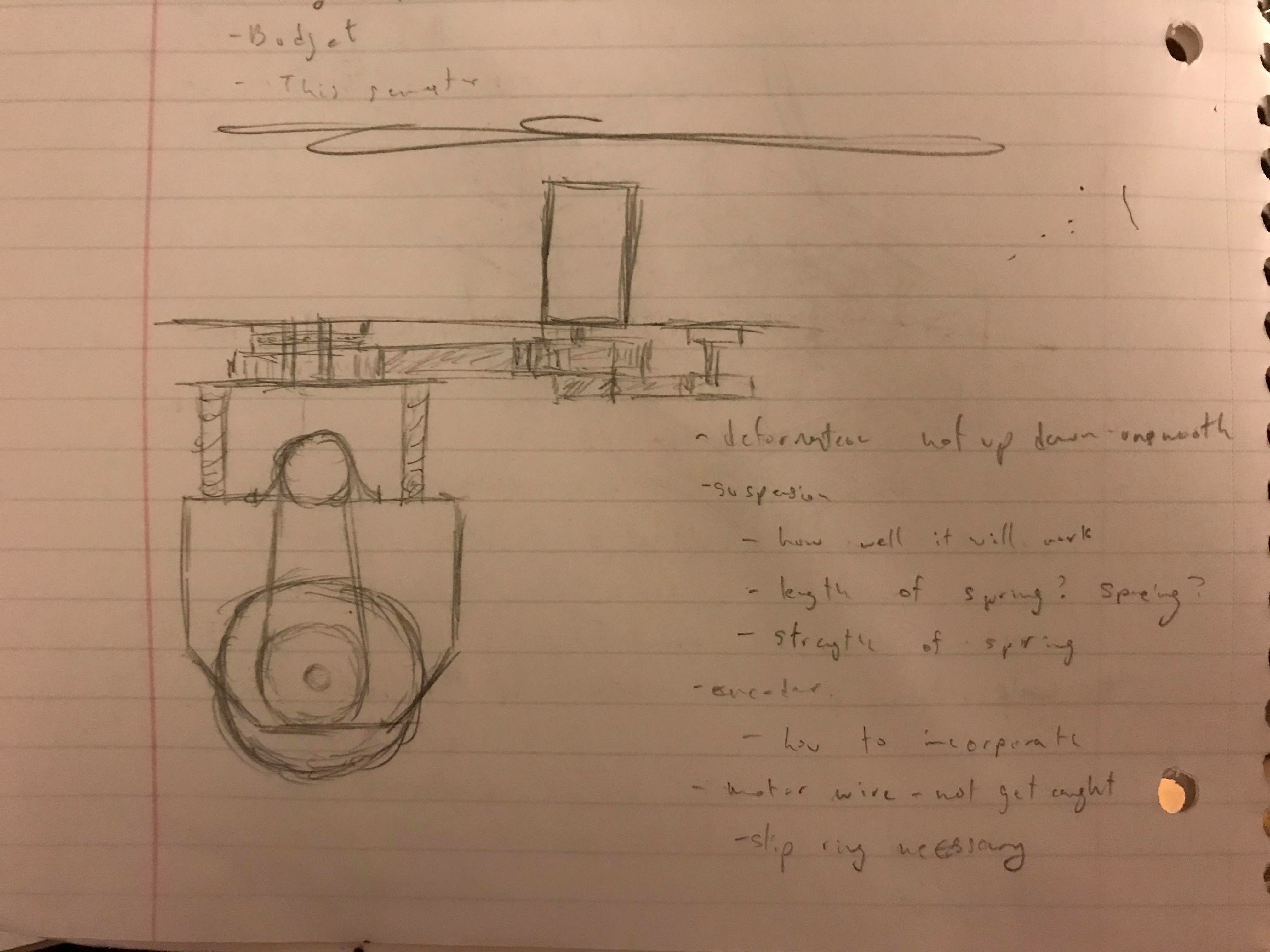
Sketched design for swerve module
The complexity of designing swerve drive lies in the different components of each wheel module. To put it simply, there are two motors per wheel: one that drive the wheel, and one that turns the wheel towards the angle that it is supposed to rotate towards. The driving motor is typically run through a series of either pulleys or chain to the main axle that holds the wheel. The turning motor can turn the entire wheel module also through a pully or chain, as each module is free to rotate on the main frame. It would be difficult to mount the driving motor on the module, because as the module turns, the wires of the motor can easily tangle. As such, the driving motor is mounted to the main frame and uses bevel gears in order to connect with the main axle.
Attempt #1
My first attempt at modeling a swerve drive in CAD is shown below. The module was to be made out of wood, with standoffs supporting the ends together. The thrust bearing located at the top would enable the module to rotate smoothly using the sprocket, also on the top.
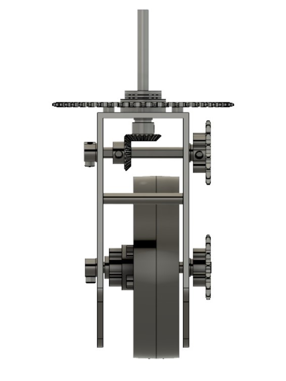
There were several issues with my first design. Firstly, the main axles were thin. This meant the axles were more likely to bend, which is deadly to swerve because it will not longer be able to move smoothly. Additionally, everything was secured using set screws. This would be an issue with repeated use, as they would eventually get loose and it would be problematic to constantly have to re-tighten them. Additionally, with the sprockets and chain being on the outside, it could risk getting caught while manuevering around objects. The thrust bearing on top would also have be redesigned, as it took up too much space and force me to use a sprocket that was way too large.
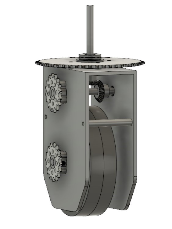
Attempt #2
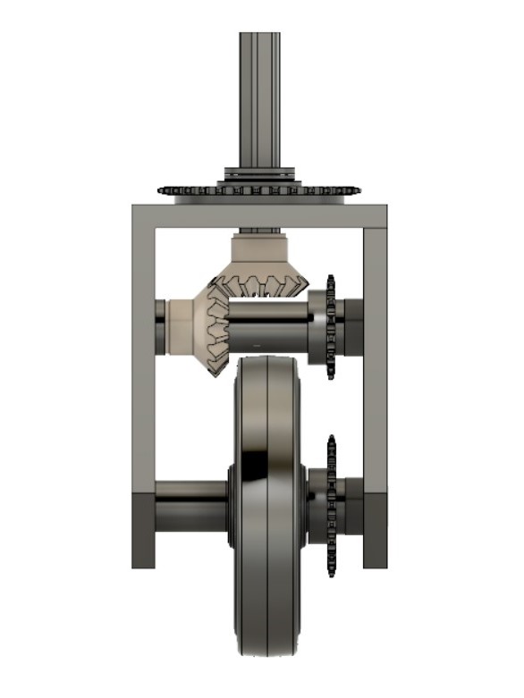
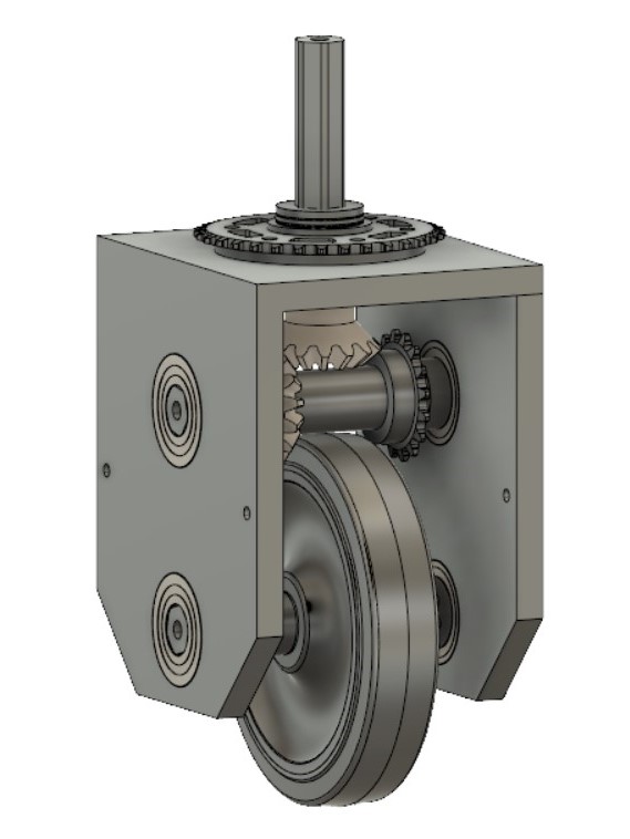
The second model is much sturdier than the first. The main change is that it utilizes 3/8th inch hex axles. These are a lot stronger than the original axles. Additionally, they are redesigned to have bearings on each side, so they will spin much smoother. Having hex axles also negates the need for set screws, which is much more convenient. The module frame will be 3D printed, which allows for precise fitting of the bearings and axles.
Due to the costs of building swerve and further potential to improve the design, I have yet to build a full prototype of this model. Hopefully if I'm ever rich I will be able to make this come to fruition, and use it well in one of my projects.